For years, multi-homing in VXLAN BGP/EVPN fabrics with Cisco Nexus switches meant one thing: vPC. It works very well; two-switch redundancy, familiar operational model, no need to deeply understand EVPN’s native multi-homing details. At the same time, vPC has always carried operational overhead: peer-links, keepalive link, the potential peer-link bandwidth limitation, and the hard ceiling of two switches. With NX-OS 10.6(1), Cisco finally brings full native VXLAN EVPN ESI multi-homing on Nexus 9000!
This post digs into what that means and how it works.
What Problem Does VXLAN EVPN ESI multi-homing on Nexus 9000 solve?
In a VXLAN BGP/EVPN fabric, leaf switches (VTEPs) connect hosts, also called Customer Edge (CE) devices. When a CE is dual-homed to two VTEPs, we need a mechanism to:
- Advertise the host reachability from both VTEPs simultaneously: all-active.
- Prevent loops: no duplicate delivery of BUM traffic to the CE.
- Handle fast failover when one VTEP loses connectivity to the CE.
- Synchronize MAC/IP state between the two VTEPs.
Cisco Nexus vPC solves this by running a proprietary peer protocol over a physical or “fabric” peer-link. It works, but it requires two switches forming a pair. This limits us to a 2-way redundancy only, with peer-link bandwidth reserved essentially as insurance.
ESI multi-homing solves the same problem entirely through the BGP/EVPN control plane, using the VXLAN fabric itself as the synchronization medium. No dedicated peer-link, and no keepalive link. And support for 2-way, 3-way, and 4-way multi-homing from the same host.
Core Concepts
The Ethernet Segment (ES) and the Ethernet Segment Identifier (ESI)
An Ethernet Segment (ES) is the logical bundle of links that connects a CE device to one or more VTEPs. Each ES is identified by a 10-byte value called the Ethernet Segment Identifier (ESI). The ESI is configured identically on all VTEPs that share connectivity to the same CE. This is how they recognize each other as peers for a given segment.
The ESI format is: [Type: 1 byte] [Value: 9 bytes]
RFC 7432
RFC 7432 defines several ESI types. The most relevant in practice:
| Type | Name | How the value is formed |
|---|---|---|
| 0x00 | Manually configured | Operator provides the full 9-byte value |
| 0x01 | LACP-based (auto) | Derived from LACP system-ID and admin-key |
| 0x03 | MAC-based (auto) | 6-byte system-MAC + 3-byte local discriminator |
ESI Types on Cisco NX-OS 10.6(1)
On Cisco NX-OS 10.6(1), all three types are supported, with different configuration syntax for each.
- Type 0: Allows a fully manual ESI, useful for cross-vendor interoperability.
- Type 1: Auto-derives the ESI from LACP negotiation.
- Type 3: Is the default approach: we configure a shared system-mac, and a local discriminator under the port-channel, and the switch derives the full ESI automatically as: 0x03 | <system-mac> | <ES-LD>
EVPN Route Types Involved
ESI multi-homing relies on several BGP EVPN route-types, working in concert:
Type-1: Ethernet Auto-Discovery, EAD, or A-D routes
Type-1 routes are split into two subtypes with distinct roles:
- EAD/ES: Ethernet EAD (or A-D) route per Ethernet Segment (per-ES):
-
- Fast Convergence (Mass Withdrawal): Used for fast convergence when an ES goes down. If a link in a multihomed segment fails, the VTEP can withdraw a single Type-1 per-ES route instead of thousands of individual MAC (Type-2) routes. This allows remote switches to instantly stop sending traffic to that failed link. (Ethernet Tag = 0xFFFFFFFF).
- Split-Horizon filtering: In all-active multi-homing, BUM traffic arriving at a VTEP from the fabric must not be forwarded back out toward the CE if it originated from another VTEP on the same Ethernet Segment, that would cause duplicates at the CE. The ESI carried in the EAD/ES route is used to identify co-members of the segment, enabling each VTEP to filter such traffic at the data plane. For additional details, see under the DF below.
- Fast Convergence (Mass Withdrawal): Used for fast convergence when an ES goes down. If a link in a multihomed segment fails, the VTEP can withdraw a single Type-1 per-ES route instead of thousands of individual MAC (Type-2) routes. This allows remote switches to instantly stop sending traffic to that failed link. (Ethernet Tag = 0xFFFFFFFF).
-
- EAD/EVI: Ethernet EAD (or A-D) route per EVPN Instance (per-EVI):
- Aliasing: Allows a remote VTEP to load-balance traffic across all VTEPs in a multihomed group, even if it has only learned a MAC address from one of them.
- Backup Path: Indicates reachability for single-active multihoming redundancy
Type-2 (MAC/IP Advertisement)
Each VTEP in the ESI peer group re-originates Type-2 routes for MAC/IP addresses learned on the shared segment, carrying the ESI value in the route. Remote VTEPs use this to build ECMP next-hops.
Type-3 (Inclusive Multicast Ethernet Tag — IMET)
Unchanged from standard EVPN: handles BUM traffic replication.
Type-4 (Ethernet Segment Route)
Used for Designated Forwarder (DF) election between ESI peers. Each VTEP advertises its Type-4 route for a given ES, and peers use this to elect which VTEP forwards BUM traffic toward the CE (to prevent duplicates).
Designated Forwarder (DF) Election
In an all-active ESI deployment, all VTEPs can send and receive unicast traffic to and from the CE. However, BUM traffic (Broadcast, Unknown unicast, Multicast) from the fabric toward the CE must be forwarded by only one VTEP per EVI: the Designated Forwarder (DF). This prevents duplicate BUM frames and loops.
DF election happens via Type-4 routes. Two election algorithms are defined:
- Modulo-based (default method defined in RFC7432): Each VTEP in the ES peer group is assigned an ordinal based on its VTEP IP, sorted in ascending order (lowest IP = ordinal 0). Then, the DF for a given VLAN is selected by: i = V mod N, where V is the VLAN ID, and N is the number of ESI peers. The VTEP whose ordinal equals the result is the DF. For example, for 3 VTEPs and VLAN 10: 10 mod 3 = 1. The VTEP with Ordinal 1 becomes the DF.
This distributes the DF role across all peer VTEPs: for example, with two peers and VLANs 10–11, VLAN 10 goes to ordinal 0 (10 mod 2 = 0) and VLAN 11 to ordinal 1 (11 mod 2 = 1). - Preference-based: Allows manual control by assigning a preference value to each VTEP. The VTEP with the highest (or lowest, depending on the vendor) preference wins the DF role election in the segment.
In addition, to ensure all VTEPs have enough time to exchange routes before making a decision, a hold timer (usually 3 seconds by default) is used. The election only finalizes once this timer expires, preventing temporary traffic drops or duplicates during a network boot.
Then, the non-DF VTEPs drop BUM traffic received from the fabric that would otherwise be sent toward the CE.
DF and split-horizon
The DF election and split-horizon are complementary mechanisms that together prevent duplicate BUM traffic, but in opposite directions.
DF (fabric → CE): BUM traffic from the fabric arrives at all ESI peers simultaneously. Without coordination, all of them would forward it to the CE, causing duplicates. The DF election designates exactly one VTEP per VLAN to forward BUM toward the CE; the others drop it.
Split-horizon (CE → fabric → CE): BUM traffic originating from the CE is flooded into the fabric by the receiving VTEP. That flood reaches the other ESI peer, which must not forward it back to the CE, otherwise the CE receives its own traffic back. The ESI carried in the VXLAN encapsulation identifies co-members of the segment, allowing the receiving VTEP to drop it at the data plane.
Aliasing
When a remote VTEP has a Type-2 route for a MAC reachable via an ESI, it learns that MAC’s next-hop as the advertising VTEP’s IP. But with ESI multi-homing, multiple VTEPs share the same ESI. The EAD/EVI routes act as an “aliasing” signal, telling remote VTEPs: “even if you only have a Type-2 from VTEP-A, you can also forward toward VTEP-B because they share the ESI.” This is how remote VTEPs achieve ECMP toward a multi-homed CE even before seeing Type-2 routes from all ESI peers.
Multi-Homing Scale and Capability Differences
- Standard-Based Multihoming (N-way): EVPN ESI supports “N-way” multihoming, meaning a CE device can be connected to 2, 3, 4, or more VTEPs simultaneously.
- Vendor Interoperability: Because it uses standard BGP EVPN control plane mechanisms (specifically Type-1 and Type-4 routes), you can theoretically multihome a server across switches from different vendors, such as a Cisco Nexus and an Arista leaf.
- Load Balancing: In an All-Active configuration, all N-VTEPs can forward traffic for the same ESI, providing massive aggregate bandwidth to a single compute node or storage array.
- Traffic Distribution: In EVPN, this is handled by the Aliasing feature (Type-1 routes), which allows remote VTEPs to perform equal-cost multi-path (ECMP) load balancing across all VTEPs in the Ethernet Segment, regardless of which one physically learned the MAC address.
ESI Multi-Homing Modes on Cisco NX-OS
PIP vs. VIP (Anycast) Next-Hop
NX-OS supports two next-hop models for ESI multi-homing:
- PIP (Primary IP) — Unicast next-hop: Each VTEP uses its own unique VTEP IP (loopback). ECMP is built at the remote end using aliasing. This is the most flexible model and supports asymmetric topologies.
- VIP (Virtual IP) — Anycast next-hop: All ESI peers share a common anycast VTEP IP in addition to their individual PIPs. This simplifies the ECMP model (single next-hop, multiple physical paths). Similar to the vPC anycast VTEP behavior. This model eases migration from vPC-based fabrics.
Platform Support in NX-OS 10.6(1)
Today, full native ESI multi-homing is supported on:
- Cisco Nexus 9300-FX2, FX3, GX, GX2, H2R, H1 Series
- Cisco Nexus 9500 Series with 9700-GX or FX3 line cards
Important: Before 10.6(1), Nexus switches could interoperate with ESI multi-homing peers (e.g., Juniper QFX, Arista, Huawei CE) in a mixed fabric — but they could not act as full ESI multi-homing endpoints themselves. Starting with 10.6(1)F, they can.
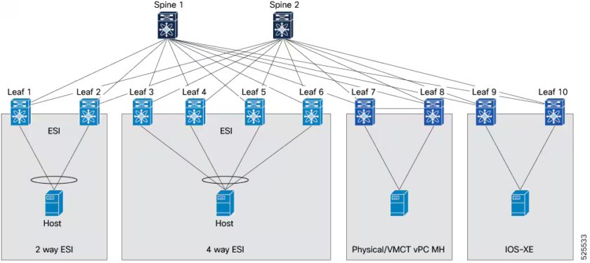
Interoperability with different ESI multi-homing solutions
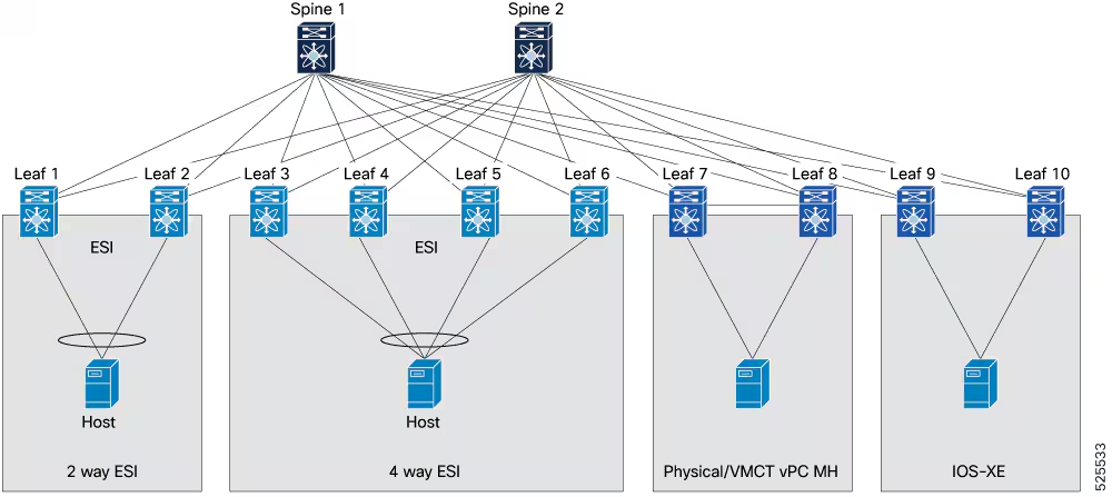
Source: Cisco.com
ESI multi-homing supports interoperability with the different vPC solutions: standard vPC (with physical peer-links) and vPC fabric peering, to establish robust and redundant host connectivity.
Important: There are some limitations in mixed deployments. This page lists the guidelines and limitations. For example, vPC or vPC fabric peering can coexist. However, each VTEP operates in either vPC-VTEP or ESI-VTEP mode, not both simultaneously.
An additional note on Interoperability
Before 10.6(1), Nexus switches could participate in an ESI fabric as non-ESI peers — meaning they could receive and process ESI-related BGP routes from other vendors and forward traffic correctly, but they couldn’t originate ESI routes themselves. This is what the “interoperability” chapter in the Cisco documentation addresses.
With 10.6(1), the Nexus 9000 is now a full first-class ESI participant, aligning Cisco’s data center switching portfolio with the approach long supported by Juniper (JunOS) and Arista (EOS).
Conclusions
EVPN ESI all-active multi-homing on Cisco Nexus is a long-awaited feature that brings the Cisco Nexus platform into full alignment with the standards and the rest of the industry. It can eliminate the vPC overhead, but most importantly, it enables true multi-vendor interoperability and scales beyond the 2-switch limit that vPC imposes.
In a future post, I would like to provide configuration and debugging examples on NX-OS. But before that, I need to upgrade my physical lab to 10.6(1) or get this version on CML, and that hasn’t happened yet.
References
- Cisco NX-OS VXLAN Configuration Guide, Release 10.6(x) — EVPN Ethernet Segment Identifier Multi-Homing
- Cisco NX-OS VXLAN Configuration Guide, Release 10.6(x) — Interoperability with EVPN multi-homing using ESI
- Juniper Networks: Understanding Automatically Generated ESIs in EVPN Networks
- Toni Pasanen’s book: Virtual Extensible LAN VXLAN
- RFC 7432 — BGP MPLS-Based Ethernet VPN
- RFC 8365 — A Network Virtualization Overlay Solution Using Ethernet VPN (EVPN)
Images source: Cisco.com
Hi Jerome
Were you able to test EVPN-MH on N9Kv with nexus9300v64.10.6.3.F? In my case I was not able to configure it since the command “evpn multihoming” is not available.
Any hints are appreciated
Cheers
Lukas
Hi Lukas,
Thank you for your comment.
As I mentioned in my post, I’m unfortunately not yet able to test the feature. I need to update my lab to be able to do so. But as soon as I do it, I’ll update this post or create a new post with examples and outputs. I’ll also do the same with my physical lab, to see it working with real devices.
Cisco NX-OS supports either vPC-based EVPN multi-homing or ESI-based EVPN multi-homing, but not both simultaneously. So if the command is not available, it could be that there is a conflict with the vPC feature. Did you remove it?
It could also not be supported on N9Kv yet. I’m sorry, but currently I don’t have this information.
I hope it helps.
Best,
Jerome